Preface
Welcome!
This is an introductory guide to writing the base software for a FIRST Tech Challenge robot within the MBHS Student Robotics Club. This quickstart is designed to assist new programmers in creating a robot configuration and simple TeleOp.
BunyipsLib for Rookies
 Covered in this guide is the operation of BunyipsLib v7.3.2 in the BunyipsFTC project.
This guide is an introduction to setting up a robot's software, and bootstrapping a basic configuration that can be expanded for more advanced features. Be sure to read the BunyipsLib Wiki for BunyipsLib-specific and advanced operations.
important
This guide is written as a basic bootstrap and quickstart for a BunyipsFTC robot using BunyipsLib. Hence, this guide is only valid for robots that use the REV Robotics Control Hub, and the extent of this guide is limited to simple TeleOp.
This guide is ordered sequentially. Use the arrows on the side of the screen or the navbar on the left to progress through the quickstart.
Additional resources
- Learn Java For FTC, an introduction and tutorial for the base FTC SDK
- BunyipsLib Wiki
- BunyipsLib API docs
BunyipsLib for Rookies. Copyright (c) 2025 Lucas Bubner, MBHS Student Robotics Club, under the MIT License.
Configuring Android Studio
Setting up Android Studio is usually a one-time process. Android Studio is the interface used between the code and robot.
https://developer.android.com/studio
You will need a GitHub account with access to the Murray-Bridge-Bunyips organisation (or to use the MBHSRobotics shared account).
For MBHS Student Robotics Club members, you can follow this guide in the shared drive to get your account set up. Note you will need a mentor to add you to the organisation
and add your user to the BunyipsFTC GitHub team if not using the shared account.
First-time setup
For new laptops, you will need to Clone Repository of URL: https://github.com/Murray-Bridge-Bunyips/BunyipsFTC.
Once the project is loaded, you must change the branch you are on. To do this, click stable in the top left:
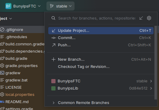
Then, press stable >:
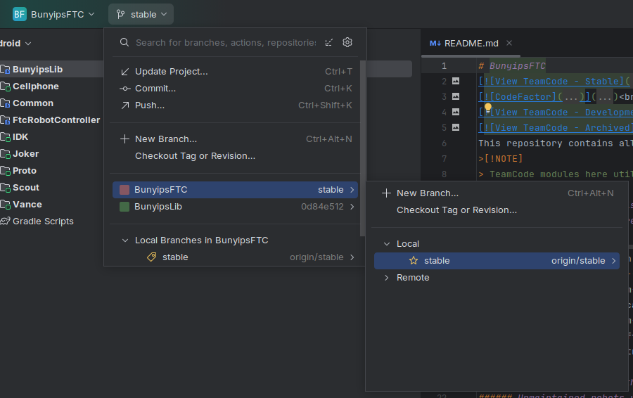
Open Remote, origin, devid-heath and click Checkout.
You are now on the development branch of BunyipsFTC. You can now Commit and Push your changes from Android Studio to upload them to the cloud.
Configuring BunyipsLib
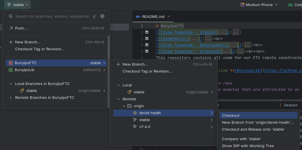
Before you proceed with programming, you will also need to change to the latest commit (master branch) of BunyipsLib.
Open the branch menu shown before, and this time click on BunyipsLib. Open Remote, origin, master, and click Checkout.
Your computer is now configured to use BunyipsFTC. These steps do not need to be repeated for this computer.
Once Gradle completes syncing (you can manually initialise a sync with Ctrl+Shift+O), the Android view on the left should display robot files.
Gradle and Git extras
Gradle AGP upgrade
tldr; do not press this button to upgrade the AGP if it shows up.
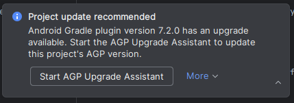
More information can be found at this Cookbook article.
"Dubious ownership" when trying to use Git
You may have some problems if Git reports dubious ownership over the BunyipsLib/BunyipsFTC project.
The error may have text like:
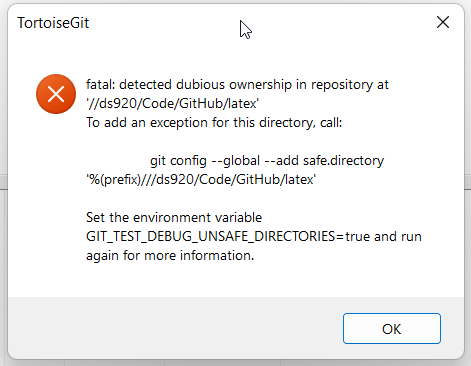
This can happen if the BunyipsFTC project is on another drive.
If you're on a club laptop, open cmd (Command Prompt) in Windows, and run:
git config --global --add safe.directory "*"
*note: this command should only be run on club laptops
Java JDK target not 17
Sometimes, building may fail since the Gradle JDK version is too recent.
If you get compilation issues from Java version, change your JDK version to 17.
To do this, go to Android Studio settings, then Build, Execution, Deployment > Build Tools > Gradle, then change
the Gradle JDK field to one that is version 17. I recommend clicking Download JDK and downloading BellSoft Liberica 17.
After this perform a Gradle sync and the code should build.
tip
Ctrl+Shift+O will Gradle sync. Double tapping Right Shift, then searching for "Compile All" and running Compile All Sources will compile everything locally.
Gradle doesn't build while connected to the robot wirelessly (after update or first time)
You may encounter build problems when updating BunyipsLib, or building for the first time, as Gradle fails to grab dependencies if wirelessly connected to the robot.
note
It is advised to Git Pull every time you open the project again. If BunyipsLib has updated, run a Gradle sync and Compile All.
The problem can be resolved by building the source code locally and with access to internet. It will not work if trying to build while connected to the robot's Wi-Fi if you don't have these dependencies locally.
To compile all sources, double tap Right Shift, then search for "Compile All" and run Compile All Sources while connected to a proper Wi-Fi network. You can then connect back to the robot to build to it as normal and for subsequent builds.
Wirelessly connecting to the robot
In order to deploy code efficiently, it is important to be able to connect to the robot wirelessly.
While a cable will provide immediate connection, a helpful plugin called ADB Wi-Fi be installed to assist in connecting to the robot over the Wi-Fi.
note
Wireless connection to the robot also works when the REV Hardware Client is open. Installing the plugin is still required.
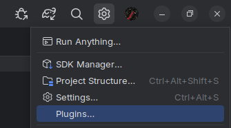
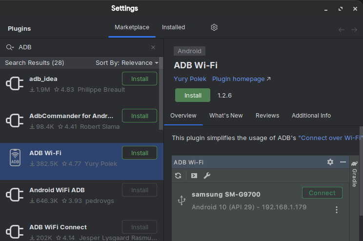
Installing ADB Wi-Fi
To install, open the settings cog and click Plugins:
Go to the Marketplace, and search ADB Wi-Fi. Install the plugin by "Yuri Polek":
Using ADB Wi-Fi
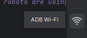
When connected to the robot's Wi-Fi network (e.g. 15215-RC-A, 22407-RC, FTC-Qagb) while the robot is on, you can access ADB Wi-Fi in the right panel:
Initially, there will be no devices in here. You can add a robot by connecting one over USB, then a green Connect button will appear. Once connected, USB can be disconnected. You won't have to connect over USB in future occasions as it will remain in the menu.
Simply press Connect while the robot is on, and you are connected to the Wi-Fi. This process may happen automatically on connection.
Debugging ADB Wi-Fi
Sometimes, pressing Connect does not work, and this is a common issue. There are a few ways to resolve this.
- Reconnecting your Wi-Fi network
- Restarting Android Studio
- Restarting the robot by the power switch
- Restarting REV Hardware Client (if used)
If none of these work, connect via USB again.
Deploying your code
When it is time to deploy your code to the robot, connect to it via Wi-Fi or USB. Ensure to select the correct robot from the build menu:
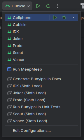
Sloth Loads (if implemented) can be selected as well from this list.
You should see "REV Robotics Control Hub" (or similar) to the left of the selector box.
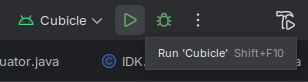
When it is time to deploy, press the green play button. The play button may also be a green "refresh" button, but it is the one to the left of the green bug.
Full Gradle builds can take upwards of a few minutes, which is why Sloth Loads are beneficial.
And remember, you can't press a button wrong.
Making a new robot
With access to the BunyipsFTC project complete, you are now able to access the software for all current robots.
If you would like to make a new robot, some configuration is required internally in the project.
These steps are also located in the "Common" directory within BunyipsFTC (file).
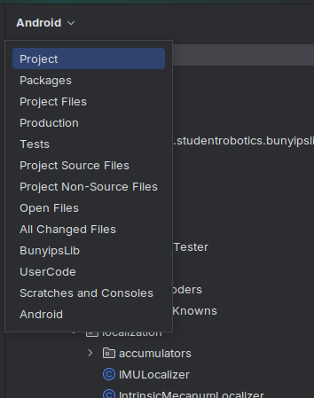
To create a new robot, you will need to think of a name for your new robot. Once you have one, switch
your filesystem view from Android to Project:
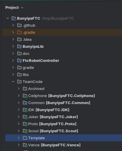
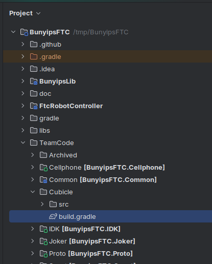
Open BunyipsFTC > TeamCode and find the Template directory:
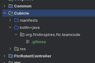
Right-click to copy and paste it in TeamCode. Input the name of your robot here. This example will use the robot name Cubicle:
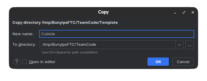
Note: The "To Directory" field in the above screenshot may not match what you get, but it should end with BunyipsFTC/TeamCode.
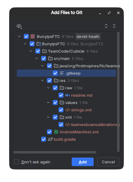
Add files to Git if you are prompted:
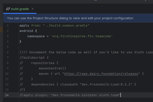
Open the new directory of your robot's name, and double-click to open the build.gradle file of your robot:
Expand the dots, then uncomment lines 1-4 inside this file:
note
You can optionally uncomment lines 6-14 to configure Sloth Load.
Sloth Load allows you to "fast build" code during rapid testing. However, this is out of scope of this guide and setup is explained by this BunyipsLib Wiki page. It is optional but recommended.
Finally, to complete setup, find the settings.gradle file in the root of the BunyipsFTC project (usually at the bottom), then open it:
At the bottom of this file, add these two lines, ensuring to substitute the example name "Cubicle" with your robot's name:
include ':Cubicle'
project(":Cubicle").projectDir = new File("TeamCode/Cubicle")
Finally, press Ctrl+Shift+O which will sync Gradle and add your configuration to the list.
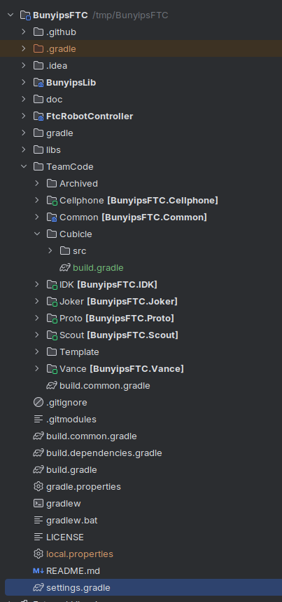
Return to Android view in the filesystem viewer. You should confirm that your robot appears in the Android view list now.
Inside your new robot directory under kotlin+java, a .gitkeep file should exist. This .gitkeep file can be deleted. This is the directory where all of your robot code will go.
Your robot is now ready to be programmed.
Mapping robot hardware
While every REV Control Hub is the same, the robots being controlled are each unique. Each Control Hub has the same number of input and output ports for motors, sensors and cameras, but, how you may utilize these ports varies from system to system. For instance, a Color Sensor V3 may be plugged in to I2C Bus 1 on one person's Hub, but another might use the same bus to host a 2m Distance Sensor.
While the Control Hub may know there is a device attached to a port, it doesn't instinctively know which information needs to be transferred back for use in an OpMode. To help our robot out we need to complete a process called hardware mapping.
For us, this is a two-step process.
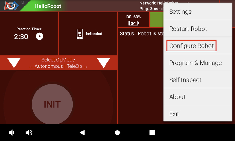
Configure Robot on Driver Hub
These instructions follow the official REV "Setting up a Configuration" resource.
-
Access the Configure Robot menu to start hardware mapping.
-
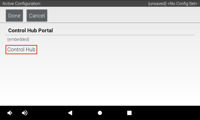
Create a New configuration for a new robot, or Edit an existing one.
-
Open "Control Hub Portal", then "Control Hub" or "Expansion Hub" to enter configuration.
-
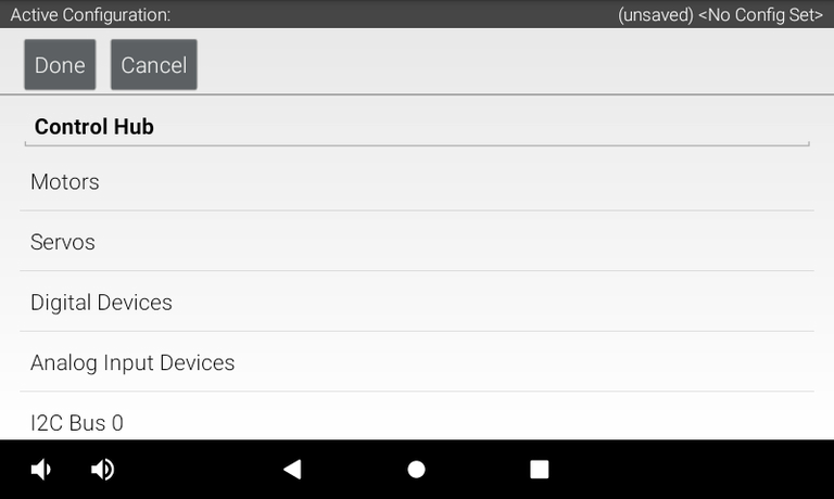
For this particular hub, this is where you will map your motor ports to names. Ensure to remember or write down these names.
 Name your hardware devices according to what they do. A motor used to lift a linear slide can be called a "lift", and drivebase motors are usually named by their position "front_back", "bl", etc. A left and right claw can be called "left_claw" and "right_claw" etc.
tip
USB cameras show up on the root screen with Control Hub Portal after pressing Scan. REV Robotics Touch Sensors (limit switches) are mapped on the N+1'th Digital Port.
- Once you've configured all devices across your Control/Expansion Hub(s), you can Save the configuration.
The Control Hub will now store these hardware mappings and you can exit the hardware configuration.
Configuration file
With your robot configured by the hardware map, creating your main RobotConfig file is the next major step.
Your configuration file is the interface between all your OpModes and the hardware devices.
- In the directory of your robot - where the previous
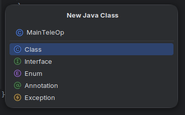
.gitkeepfile existed - right click, and create aNew > Java Class.
note
This example will still use Cubicle as the robot name. Ensure to change this to your robot name selected previously.
- Name this new Java Class the name of your robot:
-
Add File to Git if you are prompted.
-
With your main configuration file created, you can select a drivebase template to paste in below. If you'd like to be more manual with your configuration file, read the BunyipsLib Wiki page on robot configuration.
The configurations below are templates that you should copy and replace (Ctrl+A then Ctrl+V) and work from there.
Ensure to change the name Cubicle to your robot's name.
You may also want to use RoadRunner, which is used in Autonomous to create complex paths and to follow them. To learn about RoadRunner and how to use it, consult the BunyipsLib Wiki and use the RoadRunner template. RoadRunner requires a lot more setup to use properly due to the tuning process.
If you're using a Mecanum drive-
-with RoadRunner
Copy the following as your configuration:
package org.firstinspires.ftc.teamcode;

import com.qualcomm.hardware.rev.RevHubOrientationOnRobot;
import com.qualcomm.robotcore.hardware.DcMotor;
import com.qualcomm.robotcore.hardware.DcMotorSimple;
import com.qualcomm.robotcore.hardware.IMU;

import au.edu.sa.mbhs.studentrobotics.bunyipslib.RobotConfig;
import au.edu.sa.mbhs.studentrobotics.bunyipslib.hardware.IMUEx;
import au.edu.sa.mbhs.studentrobotics.bunyipslib.roadrunner.parameters.DriveModel;
import au.edu.sa.mbhs.studentrobotics.bunyipslib.roadrunner.parameters.MecanumGains;
import au.edu.sa.mbhs.studentrobotics.bunyipslib.roadrunner.parameters.MotionProfile;
import au.edu.sa.mbhs.studentrobotics.bunyipslib.subsystems.drive.MecanumDrive;

/**
 * Main robot configuration file.
 * Bootstrapped through bunyipslib-for-rookies.
 *
 * @author Your Name, Year // TODO: Set this to your name and the current year!
 */
public class Cubicle extends RobotConfig {
    public final Hardware hw = new Hardware();

    // ... SUBSYSTEMS AND OTHER PUBLIC DECLARATIONS HERE ...
    public MecanumDrive drive;
    // TODO: Add more subsystems here according to your robot's needs
    // .....................................................

    @Override
    protected void onRuntime() {
        // TODO: Change or confirm the hardware name "fl" is your Front Left Mecanum Motor
        hw.fl = getHardware("fl", DcMotor.class, (d) -> {
            // TODO: Set the direction of the front left motor here
            d.setDirection(DcMotorSimple.Direction.FORWARD);
        });

        // TODO: Change or confirm the hardware name "bl" is your Back Left Mecanum Motor
        hw.bl = getHardware("bl", DcMotor.class, (d) -> {
            // TODO: Set the direction of the back left motor here
            d.setDirection(DcMotorSimple.Direction.FORWARD);
        });

        // TODO: Change or confirm the hardware name "br" is your Back Right Mecanum Motor
        hw.br = getHardware("br", DcMotor.class, (d) -> {
            // TODO: Set the direction of the back right motor here
            d.setDirection(DcMotorSimple.Direction.FORWARD);
        });

        // TODO: Change or confirm the hardware name "fr" is your Front Right Mecanum Motor
        hw.fr = getHardware("fr", DcMotor.class, (d) -> {
            // TODO: Set the direction of the front right motor here
            d.setDirection(DcMotorSimple.Direction.FORWARD);
        });

        // TODO: Confirm an IMU exists on I2C Bus 0 called "imu" on the Control Hub
        hw.imu = getHardware("imu", IMUEx.class, (d) ->
                d.lazyInitialize(new IMU.Parameters(new RevHubOrientationOnRobot(
                        // TODO: This process follows the IMU initialisation and orientation setup. Follow instructions for direction
                        //     here: https://ftc-docs.firstinspires.org/en/latest/programming_resources/imu/imu.html#axes-definition
                        RevHubOrientationOnRobot.LogoFacingDirection.UP, // TODO: Check if FIRST logo is pointing upward relative to front
                        RevHubOrientationOnRobot.UsbFacingDirection.LEFT // TODO: Check if USB is pointing left relative to front
                ))));

        DriveModel driveModel = new DriveModel.Builder()
                // TODO: Fill out as necessary according to the RoadRunner Tuning section of the BunyipsLib Wiki
                .build();
        MotionProfile motionProfile = new MotionProfile.Builder()
                // TODO: Fill out as necessary according to the RoadRunner Tuning section of the BunyipsLib Wiki
                .build();
        MecanumGains mecanumGains = new MecanumGains.Builder()
                // TODO: Fill out as necessary according to the RoadRunner Tuning section of the BunyipsLib Wiki
                .build();
        drive = new MecanumDrive(driveModel, motionProfile, mecanumGains, hw.fl, hw.bl, hw.br, hw.fr, hw.imu)
                // TODO: Set Localizer/other parameters here (if required) according to the RoadRunner section of the BunyipsLib Wiki
                .withName("Drive");
    }

    /**
     * Contains all hardware objects used for the robot.
     */
    public static class Hardware {
        // TODO: Rewrite the comments above each hardware declaration to match your port and name configuration (e.g <Control/Expansion> <port>: <name in DS>)
        //   It is strongly recommended to do this as hardware mappings may erase themselves unexpectedly.
        /**
         * Internally mounted on Control Hub I2C 0
         */
        public IMU imu;
        /**
         * Control 0: fl
         */
        public DcMotor fl;
        /**
         * Control 1: bl
         */
        public DcMotor bl;
        /**
         * Control 2: br
         */
        public DcMotor br;
        /**
         * Control 3: fr
         */
        public DcMotor fr;
        // TODO: Add more hardware devices here according to your robot's configuration
    }
}
-without RoadRunner
Copy the following as your configuration:
package org.firstinspires.ftc.teamcode;

import com.qualcomm.robotcore.hardware.DcMotor;
import com.qualcomm.robotcore.hardware.DcMotorSimple;

import au.edu.sa.mbhs.studentrobotics.bunyipslib.RobotConfig;
import au.edu.sa.mbhs.studentrobotics.bunyipslib.subsystems.drive.SimpleMecanumDrive;

/**
 * Main robot configuration file.
 * Bootstrapped through bunyipslib-for-rookies.
 *
 * @author Your Name, Year // TODO: Set this to your name and the current year!
 */
public class Cubicle extends RobotConfig {
    public final Hardware hw = new Hardware();

    // ... SUBSYSTEMS AND OTHER PUBLIC DECLARATIONS HERE ...
    public SimpleMecanumDrive drive;
    // TODO: Add more subsystems here according to your robot's needs
    // .....................................................

    @Override
    protected void onRuntime() {
        // TODO: Change or confirm the hardware name "fl" is your Front Left Mecanum Motor
        hw.fl = getHardware("fl", DcMotor.class, (d) -> {
            // TODO: Set the direction of the front left motor here
            d.setDirection(DcMotorSimple.Direction.FORWARD);
        });

        // TODO: Change or confirm the hardware name "bl" is your Back Left Mecanum Motor
        hw.bl = getHardware("bl", DcMotor.class, (d) -> {
            // TODO: Set the direction of the back left motor here
            d.setDirection(DcMotorSimple.Direction.FORWARD);
        });

        // TODO: Change or confirm the hardware name "br" is your Back Right Mecanum Motor
        hw.br = getHardware("br", DcMotor.class, (d) -> {
            // TODO: Set the direction of the back right motor here
            d.setDirection(DcMotorSimple.Direction.FORWARD);
        });

        // TODO: Change or confirm the hardware name "fr" is your Front Right Mecanum Motor
        hw.fr = getHardware("fr", DcMotor.class, (d) -> {
            // TODO: Set the direction of the front right motor here
            d.setDirection(DcMotorSimple.Direction.FORWARD);
        });

        drive = new SimpleMecanumDrive(hw.fl, hw.bl, hw.br, hw.fr)
                .withName("Drive");
    }

    /**
     * Contains all hardware objects used for the robot.
     */
    public static class Hardware {
        // TODO: Rewrite the comments above each hardware declaration to match your port and name configuration (e.g <Control/Expansion> <port>: <name in DS>)
        //   It is strongly recommended to do this as hardware mappings may erase themselves unexpectedly.
        /**
         * Control 0: fl
         */
        public DcMotor fl;
        /**
         * Control 1: bl
         */
        public DcMotor bl;
        /**
         * Control 2: br
         */
        public DcMotor br;
        /**
         * Control 3: fr
         */
        public DcMotor fr;
        // TODO: Add more hardware devices here according to your robot's configuration
    }
}
If you're using a Tank drive-
-with RoadRunner
Copy the following as your configuration:
package org.firstinspires.ftc.teamcode;

import com.qualcomm.hardware.rev.RevHubOrientationOnRobot;
import com.qualcomm.robotcore.hardware.DcMotor;
import com.qualcomm.robotcore.hardware.DcMotorSimple;
import com.qualcomm.robotcore.hardware.IMU;

import java.util.Collections;

import au.edu.sa.mbhs.studentrobotics.bunyipslib.RobotConfig;
import au.edu.sa.mbhs.studentrobotics.bunyipslib.hardware.IMUEx;
import au.edu.sa.mbhs.studentrobotics.bunyipslib.roadrunner.parameters.DriveModel;
import au.edu.sa.mbhs.studentrobotics.bunyipslib.roadrunner.parameters.MotionProfile;
import au.edu.sa.mbhs.studentrobotics.bunyipslib.roadrunner.parameters.TankGains;
import au.edu.sa.mbhs.studentrobotics.bunyipslib.subsystems.drive.TankDrive;

/**
 * Main robot configuration file.
 * Bootstrapped through bunyipslib-for-rookies.
 *
 * @author Your Name, Year // TODO: Set this to your name and the current year!
 */
public class Cubicle extends RobotConfig {
    public final Hardware hw = new Hardware();

    // ... SUBSYSTEMS AND OTHER PUBLIC DECLARATIONS HERE ...
    public TankDrive drive;
    // TODO: Add more subsystems here according to your robot's needs
    // .....................................................

    @Override
    protected void onRuntime() {
        // TODO: Change or confirm the hardware name "left" is your left tank drive motor
        hw.left = getHardware("left", DcMotor.class, (d) -> {
            // TODO: Set the direction of the left motor here
            d.setDirection(DcMotorSimple.Direction.FORWARD);
        });

        // TODO: Change or confirm the hardware name "right" is your right tank drive motor
        hw.right = getHardware("right", DcMotor.class, (d) -> {
            // TODO: Set the direction of the right motor here
            d.setDirection(DcMotorSimple.Direction.FORWARD);
        });

        // TODO: Confirm an IMU exists on I2C Bus 0 called "imu" on the Control Hub
        hw.imu = getHardware("imu", IMUEx.class, (d) ->
                d.lazyInitialize(new IMU.Parameters(new RevHubOrientationOnRobot(
                        // TODO: This process follows the IMU initialisation and orientation setup. Follow instructions for direction
                        //     here: https://ftc-docs.firstinspires.org/en/latest/programming_resources/imu/imu.html#axes-definition
                        RevHubOrientationOnRobot.LogoFacingDirection.UP, // TODO: Check if FIRST logo is pointing upward relative to front
                        RevHubOrientationOnRobot.UsbFacingDirection.LEFT // TODO: Check if USB is pointing left relative to front
                ))));

        // TODO: If you have more motors on the left and right sides of your robot, configure them here as well.
        //    This configuration works with one motor on each side.

        DriveModel driveModel = new DriveModel.Builder()
                // TODO: Fill out as necessary according to the RoadRunner Tuning section of the BunyipsLib Wiki
                .build();
        MotionProfile motionProfile = new MotionProfile.Builder()
                // TODO: Fill out as necessary according to the RoadRunner Tuning section of the BunyipsLib Wiki
                .build();
        TankGains tankGains = new TankGains.Builder()
                // TODO: Fill out as necessary according to the RoadRunner Tuning section of the BunyipsLib Wiki
                .build();
        // TODO: Pass an Arrays.asList() instead of singletonList() with all left and right motors if you have more than one each
        drive = new TankDrive(driveModel, motionProfile, tankGains, Collections.singletonList(hw.left), Collections.singletonList(hw.right), hw.imu)
                // TODO: Set Localizer/other parameters here (if required) according to the RoadRunner section of the BunyipsLib Wiki
                .withName("Drive");
    }

    /**
     * Contains all hardware objects used for the robot.
     */
    public static class Hardware {
        // TODO: Rewrite the comments above each hardware declaration to match your port and name configuration (e.g <Control/Expansion> <port>: <name in DS>)
        //   It is strongly recommended to do this as hardware mappings may erase themselves unexpectedly.
        /**
         * Internally mounted on Control Hub I2C 0
         */
        public IMU imu;
        /**
         * Expansion 0: left
         */
        public DcMotor left;
        /**
         * Expansion 1: right
         */
        public DcMotor right;
        // TODO: Add more hardware devices here according to your robot's configuration
    }
}
-without RoadRunner
Copy the following as your configuration:
package org.firstinspires.ftc.teamcode;

import com.qualcomm.robotcore.hardware.DcMotor;
import com.qualcomm.robotcore.hardware.DcMotorSimple;

import java.util.Collections;

import au.edu.sa.mbhs.studentrobotics.bunyipslib.RobotConfig;
import au.edu.sa.mbhs.studentrobotics.bunyipslib.subsystems.drive.SimpleTankDrive;

/**
 * Main robot configuration file.
 * Bootstrapped through bunyipslib-for-rookies.
 *
 * @author Your Name, Year // TODO: Set this to your name and the current year!
 */
public class Cubicle extends RobotConfig {
    public final Hardware hw = new Hardware();

    // ... SUBSYSTEMS AND OTHER PUBLIC DECLARATIONS HERE ...
    public SimpleTankDrive drive;
    // TODO: Add more subsystems here according to your robot's needs
    // .....................................................

    @Override
    protected void onRuntime() {
        // TODO: Change or confirm the hardware name "left" is your left tank drive motor
        hw.left = getHardware("left", DcMotor.class, (d) -> {
            // TODO: Set the direction of the left motor here
            d.setDirection(DcMotorSimple.Direction.FORWARD);
        });

        // TODO: Change or confirm the hardware name "right" is your right tank drive motor
        hw.right = getHardware("right", DcMotor.class, (d) -> {
            // TODO: Set the direction of the right motor here
            d.setDirection(DcMotorSimple.Direction.FORWARD);
        });

        // TODO: If you have more motors on the left and right sides of your robot, configure them here as well.
        //    This configuration works with one motor on each side.

        // TODO: Pass an Arrays.asList() instead of singletonList() with all left and right motors if you have more than one each
        drive = new SimpleTankDrive(Collections.singletonList(hw.left), Collections.singletonList(hw.right))
                .withName("Drive");
    }

    /**
     * Contains all hardware objects used for the robot.
     */
    public static class Hardware {
        // TODO: Rewrite the comments above each hardware declaration to match your port and name configuration (e.g <Control/Expansion> <port>: <name in DS>)
        //   It is strongly recommended to do this as hardware mappings may erase themselves unexpectedly.
        /**
         * Expansion 0: left
         */
        public DcMotor left;
        /**
         * Expansion 1: right
         */
        public DcMotor right;
        // TODO: Add more hardware devices here according to your robot's configuration
    }
}
- The provided templates are compiled with a set of yellow
TODOmessages to guide you in configuring the template. - While configuring, you will need to map the hardware names from the Driver Station to within the code. These mappings are the first parameter to
getHardware.
caution
The name you enter for a particular device into Configure Robot must be the name entered as the corresponding device in the configuration file!
You now have a basic hardware configuration for your drivetrain. We will add onto this configuration file to add other hardware components, such as lifts and claws.
Adding more subsystems
With a simple robot configuration file set up and drivebase configured, adding more devices to your configuration file is essential.
To understand more about the subsystem/hardware interaction, read this page from the BunyipsLib Wiki.
Looking at other examples is also a good way of learning how to use subsystems. Review the robot code from other robots within your project.
The set of available built-in subsystems to use can be found on this page of the BunyipsLib Wiki.
A table is presented below describing the uses of some hardware devices and corresponding subsystem.
| Subsystem | Hardware | Use case |
|---|---|---|
| Drivebases (previous section) | Varying # DcMotor | Robot locomotion. |
HoldableActuator | 1x DcMotor, varying # TouchSensor | Any encoder-enabled motor used for precise control. Integrates limit switches autonomously. |
Actuator | 1x CRServo | Any encoder-disabled motor/servo used to rotate. |
Switch | 1x Servo | Standard subsystem to control a Servo. Not related to limit switches. |
DualServos | 2x Servo | Runs two Servo instances together. Simplified version of Switch. |
note
This list is not extensive and more information is available on the wiki.
Pages within this subsection will demonstrate some simple purpose hardware and subsystem configurations commonly used within robots.
Vertical lift
The vertical lift is a very commonly used subsystem.
Since a vertical lift will rely on an encoder-driven motor, the HoldableActuator subsystem will be used.
tip
Since HoldableActuator is designed to be as generic as possible, HoldableActuator can be used for any type of actuator that has a motor! (e.g. rotators, winches, double-jointed arm with one HoldableActuator per arm)
A vertical lift will be used as the example here.
Adding a vertical lift to your config
To your Hardware static class in your configuration file, add a new DcMotor:
public static class Hardware {
    // ...
    public DcMotor lift; // Add this line
}
Then, add the declaration of a HoldableActuator subsystem in your configuration public declaration area:
public class Cubicle extends RobotConfig {
    public final Hardware hw = new Hardware();

    // ... SUBSYSTEMS AND OTHER PUBLIC DECLARATIONS HERE ...
    public HoldableActuator lift;
    // ...
}
important
By default, the vertical lift will be running the default PID controller.
Configuring PID controllers and the BunyipsLib-provided drop-in Motor class are out of scope of this guide, and
are better covered in the IO section of the BunyipsLib Wiki.
Finally, you need to initialise your hardware and subsystem. These are currently null.
In onRuntime(), add:
@Override
protected void onRuntime() {
    // ...

    hw.lift = getHardware("lift", DcMotor.class, (d) -> {
        // TODO: Set the direction of the lift motor here
        d.setDirection(DcMotorSimple.Direction.FORWARD);
    });

    lift = new HoldableActuator(hw.lift)
            // TODO: Configurations from the below section will go here!
            .withName("Lift");
}
and ensure to change or confirm the name "lift" matches your hardware mapping set in Configure Robot.
Your motor may also be configured backwards after you test it, and you will need to change the enum from FORWARD to REVERSE.
Configuring safety
By default, HoldableActuator has limited safety features as it does not know the dynamics of your system. Several with methods are affixed to the HoldableActuator
to configure various features to improve the operation of your lift.
Limit switches
Limit switches are hardware devices defined by the TouchSensor class. To configure one, add to your Hardware static class declarations:
public static class Hardware {
    // ...
    public TouchSensor limitSwitch; // Add this line
}
and ensure to initialise it in onRuntime():
@Override
protected void onRuntime() {
    // ...

    // TODO: Ensure name matches hardware map!
    hw.limitSwitch = getHardware("limit_switch", TouchSensor.class);
}
To use this limit switch on your HoldableActuator, simply pass it as an argument to withBottomSwitch() or withTopSwitch():
// ...
lift = new HoldableActuator(hw.lift)

        // Configurations get added here on your already existing lift assignment
        .withBottomSwitch(hw.limitSwitch) // For a bottoming switch (most common)

        .withName("Lift");
Stall detection
Motors are a fire hazard when they are running for too long against a hard stop. This is called a "stall". HoldableActuator attempts to stop stall events by
autonomously checking if the current draw of the motor exceeds a set threshold for an extended period.
You may need to configure the stall current of your motor. While the default may work, manual configuration is strongly recommended doing.
To configure the stall current, you will need to find your stall current. This can be done with the integrated Hardware Tester OpMode at the bottom of the TeleOp
list and observing the Current draw in Amps as the arm is stalled.
note
Too small of a threshold will cause overreactions, whereas too high of a threshold will cause underreactions.
Once you have figured out the time interval and stall current, you can set them:
lift = new HoldableActuator(hw.lift)

        // Configurations get added here on your already existing lift assignment
        .withOvercurrent(Amps.of(8), Seconds.of(4)) // Use the values you desire

        .withName("Lift");
HoldableActuator also has a timeout for steady state, to preemptively prevent stall events if the motor does not reach a setpoint in time.
This timeout is not set by default. You can set a maximum steady state time using:
lift = new HoldableActuator(hw.lift)

        // Configurations get added here on your already existing lift assignment
        .withMaxSteadyStateTime(Seconds.of(7)) // Good default

        .withName("Lift");
Velocity profiling
HoldableActuator provides a basic motion profiler for users who do not use the more advanced SystemController features of a full Motor instance.
This motion profiler is able to determine a maximum speed at which the motor will attempt to reach, rather than using raw power controls. Using this mode can also improve system dynamics against gravity.
To define a maximum speed in ticks per second, use the following:
lift = new HoldableActuator(hw.lift)

        // Configurations get added here on your already existing lift assignment
        .withUserSetpointControl((dtSec) -> 200 * dtSec) // 200 ticks per second, change as desired

        .withName("Lift");
The options presented are not extensive. A fully configured HoldableActuator may look like the following:
lift = new HoldableActuator(hw.lift)
        .withBottomSwitch(hw.limitSwitch) // homing switch
        .withTopSwitch(hw.limitSwitchTop) // bounds detection
        .withOvercurrent(Amps.of(8), Seconds.of(4)) // stall detection
        .withMaxSteadyStateTime(Seconds.of(7)) // preemptive stall detection
        .withUserSetpointControl((dtSec) -> 200 * dtSec) // motion profiling
        .withHomingPower(0.8) // homing process power
        .withHomingTimeout(Seconds.of(2)) // homing process max duration
        .withHomingZeroVelocityDuration(Milliseconds.of(500)) // homing check interval
        .withAutoPower(0.4) // max automatic movement power
        .withLowerLimit(-1000) // lower encoder limit
        .withUpperLimit(1000) // upper encoder limit
        .withLowerPowerClamp(-0.7) // lower motor speed limit
        .withUpperPowerClamp(0.9) // upper motor speed limit
        .withName("Lift");
Reading the API documentation for HoldableActuator can assist in determining what these methods control.
Continuous spinning intake
A continuous spinning intake is a continuous rotation servo (or DC motor) that simply rotates. This guide will focus specifically on a continuous rotation servo.
The Actuator subsystem is used to control a non-encoder actuator.
Adding an intake to your config
To your Hardware static class in your configuration file, add a new CRServo:
public static class Hardware {
    // ...
    public CRServo intake;
}
Then, add the declaration of a Actuator subsystem in your configuration public declaration area:
public class Cubicle extends RobotConfig {
    public final Hardware hw = new Hardware();

    // ... SUBSYSTEMS AND OTHER PUBLIC DECLARATIONS HERE ...
    public Actuator intake;
    // ...
}
Finally, you need to initialise your hardware and subsystem. These are currently null.
In onRuntime(), add:
@Override
protected void onRuntime() {
    // ...

    hw.intake = getHardware("intake", CRServo.class, (d) -> {
        // TODO: Set the direction of the intake motor here
        d.setDirection(DcMotorSimple.Direction.FORWARD);
    });

    intake = new Actuator(hw.intake)
            .withName("Intake");
}
and ensure to change or confirm the name "intake" matches your hardware mapping set in Configure Robot.
Your actuator may also be configured backwards after you test it, and you will need to change the enum from FORWARD to REVERSE.
The intake is now configured.
Single servo
The single servo subsystem is used commonly in designs with rotators, clasps, cannons, and other "open or close" applications.
The Switch subsystem controls a single servo.
Adding a servo subsystem to your config
To your Hardware static class in your configuration file, add a new Servo:
public static class Hardware {
    // ...
    public Servo servo; // Add this line, and name the servo something more descriptive
}
Then, add the declaration of a Switch subsystem in your configuration public declaration area:
public class Cubicle extends RobotConfig {
    public final Hardware hw = new Hardware();

    // ... SUBSYSTEMS AND OTHER PUBLIC DECLARATIONS HERE ...
    public Switch servo;
    // ...
}
Finally, you need to initialise your hardware and subsystem. These are currently null.
In onRuntime(), add:
@Override
protected void onRuntime() {
    // ...

    hw.servo = getHardware("servo", Servo.class, (d) -> {
        // TODO: Set the direction of the servo here
        d.setDirection(Servo.Direction.FORWARD);
        // TODO: Scale your servo accordingly, or use methods attached to the Switch subsystem directly
        d.scaleRange(0, 1);
    });

    servo = new Switch(hw.servo)
            .withName("Servo");
}
and ensure to change the name "servo" to your hardware mapping set in Configure Robot.
Your servo may also close/open in the wrong state after you test it, and you will need to change the enum from FORWARD to REVERSE.
Your servo is now configured.
Scaling your servo range and limiting speed
The servo programmer is a nightmare to use. Hence, it is more beneficial if you have a servo-programmed range that is much wider than requirements for software to scale the range appropriately.
In the above snippet, the scaleRange(0, 1) method is exposed. Changing values here will define the new minimum and maximum range the servo can go to from 0 to 1.
It is recommended to an FtcDashboard constant to allow rapid tuning of this value. This is not covered in the scope of this guide and can be found on the IO section of the BunyipsLib Wiki.
Limiting the speed of a servo requires the use of the BunyipsLib-provided ServoEx hardware device. It can be dropped in place of the Servo class, exposing more
methods to control speed and acceleration. More information can be found here.
Double servo
The double servo is a simplified version of combining two Switch instances, used exclusively for claws that use two servos.
The DualServos subsystem controls a single servo.
Adding a servo subsystem to your config
To your Hardware static class in your configuration file, add two new Servo instances:
public static class Hardware {
    // ...
    public Servo leftServo; // Add these lines, and name the servo something more descriptive
    public Servo rightServo;
}
Then, add the declaration of a DualServos subsystem in your configuration public declaration area:
public class Cubicle extends RobotConfig {
    public final Hardware hw = new Hardware();

    // ... SUBSYSTEMS AND OTHER PUBLIC DECLARATIONS HERE ...
    public DualServos claw;
    // ...
}
Finally, you need to initialise your hardware and subsystem. These are currently null.
In onRuntime(), add:
@Override
protected void onRuntime() {
    // ...

    hw.leftServo = getHardware("leftServo", Servo.class, (d) -> {
        // TODO: Set the direction of the servo here
        d.setDirection(Servo.Direction.FORWARD);
        // TODO: Scale your servo accordingly or as additional arguments to the DualServos constructor
        d.scaleRange(0, 1);
    });
    hw.rightServo = getHardware("rightServo", Servo.class, (d) -> {
        // TODO: Set the direction of the servo here
        d.setDirection(Servo.Direction.FORWARD);
        // TODO: Scale your servo accordingly or as additional arguments to the DualServos constructor
        d.scaleRange(0, 1);
    });

    claw = new DualServos(hw.leftServo, hw.rightServo)
            .withName("Claw");
}
and ensure to change the names "leftServo" and "rightServo" to your hardware mapping set in Configure Robot.
Your servos may also close/open in the wrong state after you test it, and you will need to change the enum from FORWARD to REVERSE.
Your claw is now configured.
Writing an iterative TeleOp
With all of your hardware tediously configured, it's time to write an OpMode to control this hardware.
The scope of this guide will demonstrate a basic iterative TeleOp for a robot configured with a HoldableActuator vertical lift, MecanumDrive drivebase, and DualServos claw.
important
Autonomous operation and advanced TeleOp composition is only available in the task-based paradigm.
An iterative TeleOp is fast and simple but advanced development of such an OpMode is ill-advised. The BunyipsLib wiki describes Tasks, Scheduling, and Command-based in such cases.
TeleOp template
In the directory of your robot, right click, and create a New > Java Class. This will be your main TeleOp class.
Remove all contents of this file and paste in the below template, ensuring to replace "Cubicle" with your robot name:
package org.firstinspires.ftc.teamcode;

import com.qualcomm.robotcore.eventloop.opmode.TeleOp;

import au.edu.sa.mbhs.studentrobotics.bunyipslib.BunyipsOpMode;
import au.edu.sa.mbhs.studentrobotics.bunyipslib.BunyipsSubsystem;

/**
 * Primary TeleOp.
 * Bootstrapped through bunyipslib-for-rookies.
 *
 * @author Your Name, Year // TODO: Set this to your name and the current year!
 */
@TeleOp(name = "TeleOp")
public class MainTeleOp extends BunyipsOpMode {
    private final Cubicle robot = new Cubicle();

    @Override
    protected void onInit() {
        robot.init();
        // TODO: Add any additional initialisation code here

    }

    @Override
    protected void activeLoop() {
        // TODO: Add your active looping code here

        BunyipsSubsystem.updateAll();
    }
}
Since all of the tedious configuration is abstracted into the configuration class, OpModes are simple to construct.
The basic units of work within a BunyipsOpMode are the two methods, onInit(), and activeLoop().
onInit() is fired exactly once when the INIT button is pressed.
activeLoop() is called repeatedly (up to 200 times/sec) after the PLAY button has been pressed, until the OpMode is stopped.
The generic initialiser, robot.init() handles calling the onRuntime() method as defined in your RobotConfig, as well as checking
for hardware map name mismatches.
The static method BunyipsSubsystem.updateAll() batch dispatches all hardware changes by calling .update() on every subsystem constructed at initialisation.
Without this method, you would have to call .update() on all of your subsystems (e.g. drive.update(), lift.update()).
Adding functionality
This OpMode will appear on the Driver Station under the name "TeleOp" under the TeleOp list after you have deployed your code. However, it won't do anything meaningful at the moment.
The job of the TeleOp is to take Gamepad input from both gamepads and command the exposed subsystems you defined in your configuration file.
warning
The Y axis on sticks are inverted, meaning that pushing them fully upwards will return -1. This is an intended SDK feature. The output of left_stick_y and right_stick_y should be negated if you're expecting them to be opposite.
Some examples are provided for commanding common components in a TeleOp.
tip
This phase is when you should talk to your drivers about what controls they want!
Commanding a Mecanum drive
The standard Mecanum controls is the left stick is used for translation and the right stick is used for rotation.
It is assumed this control is on gamepad1.
Inside the activeLoop(), add:
double forward = -gamepad1.left_stick_y;
double strafe = -gamepad1.left_stick_x;
double rotation = -gamepad1.right_stick_x;
robot.drive.setPower(Geometry.vel(forward, strafe, rotation));
You will need to add the import statement:
import au.edu.sa.mbhs.studentrobotics.bunyipslib.util.Geometry;
which you can do through Android Studio by hovering over the red Geometry and clicking Import class.
Commanding a lift
The standard lift controls is that an analog stick is used to power the motor in either direction, with idle being stationary.
It is assumed this control is on gamepad2.
Inside the activeLoop(), add:
robot.lift.setPower(-gamepad2.left_stick_y); // TODO: Select an appropriate stick
Commanding opening and closing claws
The standard claw controls is that a button is used to open the claws, and a button is used to close the claws.
It is assumed this control is on gamepad2.
Inside the activeLoop(), add:
// TODO: Select appropriate buttons (currently A and B, but can be any button on the controller)
//     You can also choose whether you only want to adjust one claw.
if (gamepad2.a) {
    claw.open(DualServos.ServoSide.BOTH);
}

if (gamepad2.b) {
    claw.close(DualServos.ServoSide.BOTH);
}
Optional toggles and rising edge detection
Sometimes, it is desired to instead toggle the state of the claws. However, naively calling
claw.toggle() presents an issue. Since the activeLoop() runs so quickly, pressing the button will
toggle the claw several hundred times a second, instead of firing only once.
This does not matter for methods that only set one state, but since a toggle mutates state, it will be toggled repeatedly.
A rising edge detector is built into the gamepads, which fires only on the "rising edge" of the gamepad signal.
Inside the activeLoop(), to toggle the claws use:
// TODO: Select appropriate button (currently X)
if (gamepad2.getDebounced(Controls.X)) {
    claw.toggle(DualServos.ServoSide.BOTH);
}
Congratulations! At this point in the guide, you have now constructed a functional RobotConfig and simple TeleOp using BunyipsLib.
Further steps involve closely reading the BunyipsLib API and Wiki documentation, particularly around command-based, Autonomous, and advanced subsystem interaction.
AdvantageScope Lite quickstart
The BunyipsFTC project is equipped with AdvantageScope Lite, a web dashboard similar to FtcDashboard that provides robot diagnostics, log analysis and data visualisation tools.
note
AdvantageScope does not rely on BunyipsLib! It works seamlessly with the logs produced through RoadRunner's log system.
AdvantageScope is a tool that will be generally available to all FTC teams after the 2027 control systems merge, but an early port has been made to support current FTC robots.
important
Before using AdvantageScope, it is important to first know the capabilities of the FtcDashboard first. AdvantageScope is very similar in nature to FtcDashboard but provides greater emphasis on log recall and data visualisation. AdvantageScope can be too advanced for what you need.
Review the FtcDashboard section of the BunyipsLib wiki before proceeding.
Accessing AdvantageScope
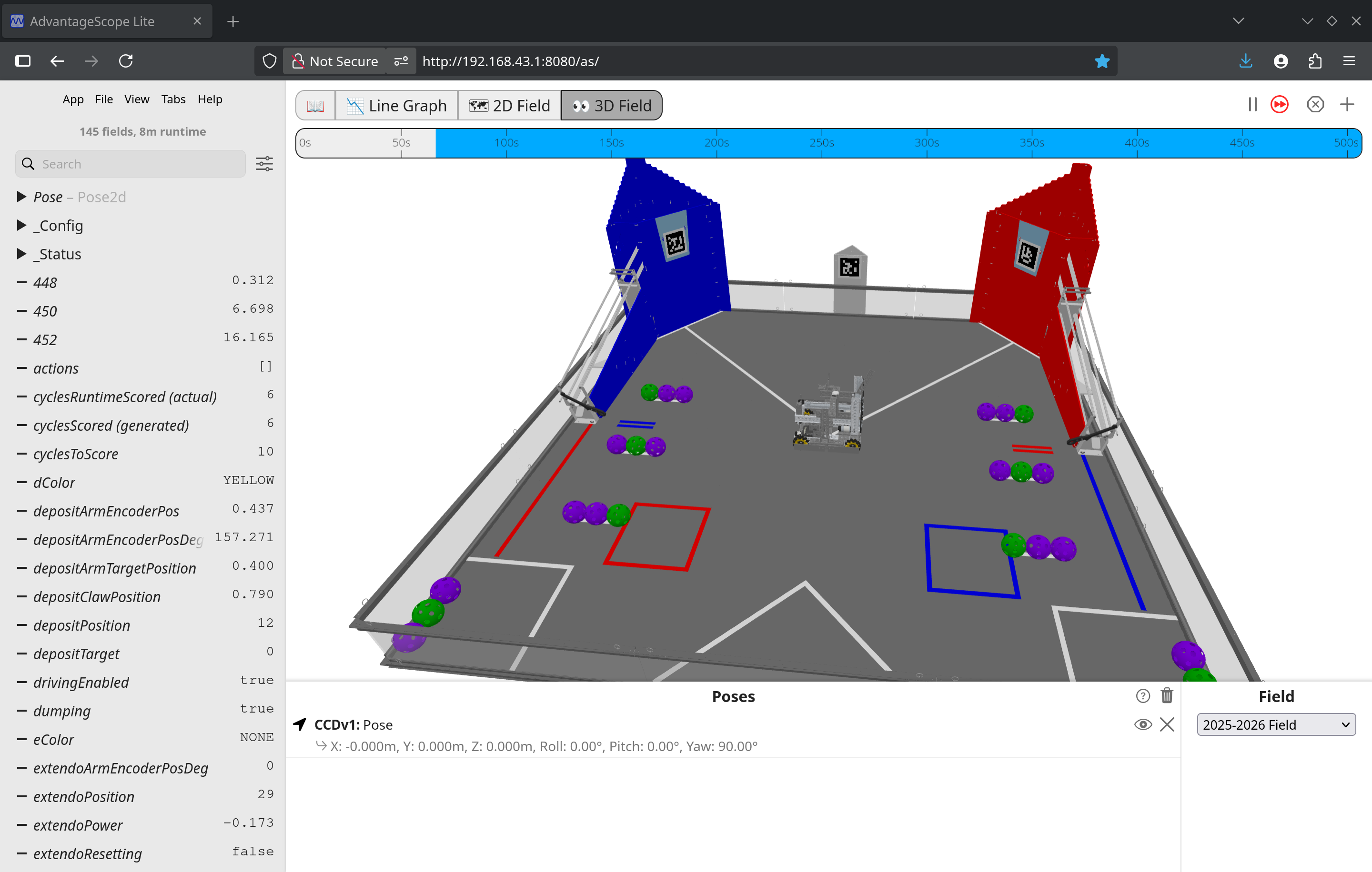
While connected to the robot, navigate to http://192.168.43.1:8080/as for a Control Hub.
The web interface will automatically connect to the FtcDashboard socket and provide data through AdvantageScope.
Telemetry attached to an FtcDashboard TelemetryPacket or through the BunyipsLib DualTelemetry object will display on the live view.
Uploading the field overlay
By default, the field overlay for the current season is not uploaded to the robot. You will need to upload the asset files to the robot. This process only has to be done once.
From AdvantageScope-Lite-FTC:
Custom assets may be uploaded as zip files through the File → Upload Asset button. Zip files can contain any folder structure, multiple assets, and even other zip files. You can download premade assets from https://github.com/Mechanical-Advantage/AdvantageScopeAssets/releases.
The files you will need to upload to access the current FTC fields in 2D and 3D are in the AllAssetsDefaultFTC.zip bundle.
You can download it here.
Uploading other assets can include CAD models of your robot which can be learnt about further in the official AdvantageScope docs.
Visualising the robot
With the correct assets, you can start the 2D Field or 3D Field and select the season field in the bottom right. To visualise your robot, you will need valid localisation.
This is covered in the RoadRunner section of the BunyipsLib wiki.
To visualise the position of the robot live, simply drag the "pose Pose" Pose2d object into the Poses area on AdvantageScope with a field selected.
 (Example image from the AdvantageScope-Lite-FTC README)
Recording information to logs
warning
Logs will not be generated for OpModes that are started through FtcDashboard as the appropriate logging hooks won't be called. OpModes must be run from the Driver Station to capture logs.
The RoadRunner FlightRecorder is used to record information to a log file. This log file can be read back and visualised later through AdvantageScope.
note
Reading logs back also works with AdvantageScope for desktop! However, this quickstart will use the web version on an active robot as accessing the log files is streamlined and automatic.
Several channels of information, including current pose data, are automatically sent to the FlightRecorder internally through the RoadRunner drive instances.
BunyipsLib also automatically records the status and essential state of primary subsystems (e.g. HoldableActuator) to the log files.
You are able to view these log schemas live through AdvantageScope and FtcDashboard by calling Dashboard.logLiveSchema(...), and passing in the subsystems you want
to view live for compatible subsystems. Drive subsystems are logged by default through the Accumulator.
Replaying logs
tip
Log files can be accessed directly from the robot for local use by going to http://192.168.43.1:8080/logs! More info here.
To replay a log through AdvantageScope Lite, you can find ones on the robot Under File -> Open Logs.
warning
The timestamp on the logs is dependent on the system clock on the Control Hub, which may be in the past, future, or completely inaccurate!
Data recorded by the FlightRecorder will appear on the replay.
Further use
AdvantageScope Lite is new software, and the official docs can provide good information on what you can use AdvantageScope for.
Thanks to j5155 for providing the j5155/AdvantageScope-Lite-FTC project!
'First Tech Challenge: DECODE: Stars Align: Will of the Holy Order: Final Dance: Rev 2: Reload: PC Port (2025)' Third Semester Secret Judge Boss Battle
Conditions for Battle
- Must have access to the Third Semester by ranking up Giulio (Tower Confidant) to Rank 8 by 31/11 and winning the Qualifiers event on 16/11
- Must have ranked up John FIRST (Temperance Confidant) to Rank 8 by 5/12
- Must have chosen the "FIRST Refs are so stupid" dialogue choice at the Qualifiers event when talking to Cooper (Hermit confidant) on 16/11
- (OPTIONAL) Heath (Hierophant confidant) can be Rank 7 by 4/12 for additional dialogue prior to fight
- (OPTIONAL) If enough scouting data is collected on a team that is placed in the Bottom 5 overall at the time of the battle, they will provide support during the fight
To trigger battle:
- During the "Semi-Finals" battle on 7/12, before endgame all robots must already park, two robots must be parked on the ground, in their alliance's zone, while the other two robots must head to the opposing alliance's zone to park on top of the currently parked robot.
- This will give all teams a yellow card
- After this sirens will ring, at which point all robots must be firmly placed on the ground
- After a cutscene, the Judge Robot will descend from the ceiling
IMPORTANT: The Judge Robot deals fatal damage to any robots it lands on top of. Make sure all robots are as far away as possible from the top center of the field to avoid damage
Fight Information
The Judge
- The Judge Boss Fight has 10,000 HP, far more then any vanilla boss (barring the final boss's final phase, which is exclusive to the New Game++ exclusive difficulty 'Ultra Diarrhea Death')
- Is the only component that deals damage to overall health bar
- The Judge is equipped with 2 saw blades mounted onto it's arms
- The saws are it's main methods of attacking and all attacks made by the saws use the Sharp element type
- Sharp type attacks deal extra damage to robots without extra armour or accessories that negate Sharp damage
- It's size exceeds the legal robot size by 2 times
- May occasionally use Shock based attacks, which have a high chance of applying Paralysis
- If a Shock move is landed with a Critical on a robot that is not blocking and has an exposed control hub, there is a 100% chance of applying Temporary Shutdown, another exclusive status effect borrowed from the final boss
- These moves are always telegraphed by a loud buzzing and spark effect on The Judge 1 turn prior
- If The Referee is defeated prior to the Judge, the Judge gains an extra turn, during which it's attacks deal half damage
The Head Referee
- Has 1000 HP, independent of the main Judge component
- Upon this health reaching 0, they will be incapacitated for 3 turns (18 seconds)
- While incapacitated, the main Judge component takes 1.5x damage and deals 0.8x damage
- After the 3 turns is up, they will restore full health and resume battle
- They are resistant to most types of attack, exclusions being that they fully block Water based attacks and take slightly extra damage to Artefact based attacked
- Has the ability to Smite a robot:
- Deals 50% of the robot's base health
- Type is Almighty, meaning it is impossible to be resistant to smiting
- Has the chance to inflict Paralysis for 3 turns (18 seconds)
- Is signified 4 turns (24 seconds) earlier, with the targeted robot signified 1 turn before smiting
- Blocking the smite reduces damage, changes applied status effect to Slow+, and also reduces chance of the effect landing
- May periodically apply status effects such as Paralysis, Slow, Rage (robot begins moving randomly and wildly for 5 seconds), and Confusion (robot attacks may be redirected to allies) that last between 2-4 turns
- They are incapable of casting status effect spells while charging a Smite
- Upon being knocked down six times, they will be permanently incapacitated
- If the Referee has been knocked out less than 4 times when The Judge is killed, it will enter a rage state
- Enters the field to manually attack robots
- Will pick up a robot, stopping it from performing any actions
- Team members also are unable to apply any effects or heal the captured robot
- After 2 turns, it will slam the robot down, dealing 95% damage
- If it lands on a robot, that robot will take damage equal to (robot weight in KG x 20)
- Will pick up a robot, stopping it from performing any actions
- Does 2x damage
- Takes 1.7x damage (health is equivalent to (700 x (6 - times knocked down))
- Enters the field to manually attack robots
- Otherwise, the Head Referee will die with the Judge
Unique Mechanics
Human Player (Neutral)
- Both Human Players have a chance to make an Artefact type attack at either the Judge or the Head Referee
- Human Players with better Accuracy stats have a higher chance of landing critical hits on the Head Referee, which can temporarily stun them
- The Human Player has a finite stock of Artefacts, which must be resupplied by
Head Referee Fist Fight
- Every 5 turns (30 seconds), there is a 20% chance for both Human Players to leave their stations to spend the next 5 turns fist fighting the Head Referee
- While the Head Referee is fighting the Human Players, it cannot charge any Smite attacks or cast status effects on robots
- Human Players deal damage equivalent to (player strength x 10)
- To mimic the Smite Ability, the Head Referee has a Taser, which deals Smite damage for some reason
- Every turn, Human Player's Agility are used to determine if they are hit by the Head Referee's Smite attack
- Upon hit, they are knocked down, and will not be revived until the designated 5 turn time slot is finished
- The Human Players return to their station if either the Head Referee is downed, or the 5 turn time period finishes
- If one or both of the Human Players have the Vengeful trait, they will body slam the Head Referee after knocking them out, which is equivalent to an extra knock out.